
Assembly Line Workbench Layout Best Practices: Balancing Operations, Materials, and Aisles
Who Needs to Rethink Their Assembly Line Workbench Layout?
Manufacturing planners in electronics assembly, automotive parts production, and hardware mold workshops frequently encounter a common bottleneck: workstations that look functional on paper but create congestion, excessive walking, or material handling delays in practice. The root cause is rarely the workbench itself—it is the spatial relationship between the workbench, material staging zones, and operator movement paths.
If your facility is experiencing frequent tool search times, WIP (work-in-progress) pile-ups between stations, or forklift-pedestrian conflicts near assembly benches, the layout—not just the equipment—needs adjustment.
The Three Zones of an Assembly Line Workbench Layout
An effective assembly line workbench layout divides each station into three functional zones. Understanding these zones is the prerequisite for selecting the right workstation equipment.
Zone 1: The Active Assembly Area
This is the primary work surface where operators perform value-added tasks. The workbench here must support the combined weight of fixtures, partially assembled components, and hand tools. For heavy-duty applications such as automotive parts assembly or hardware mold fitting, workbenches built with 100×50×1.5mm C-type cold-rolled steel frames provide a total load capacity of up to 1,000 kg, ensuring long-term structural stability under continuous use.
Desktop selection matters equally. A 50mm composite desktop (typically high-density fiberboard with a steel or laminate surface) offers a balance of impact resistance and ergonomic comfort. For environments requiring ESD protection, such as electronics assembly, anti-static desktops or grounded mat overlays become necessary—though these are distinct product configurations, not universal add-ons.
Zone 2: Tool and Fastener Staging
Operators should not walk to a central tool crib for every fastener or torque wrench. Best practice places frequently used tools within arm's reach, either in integrated drawers or on overhead pegboards.
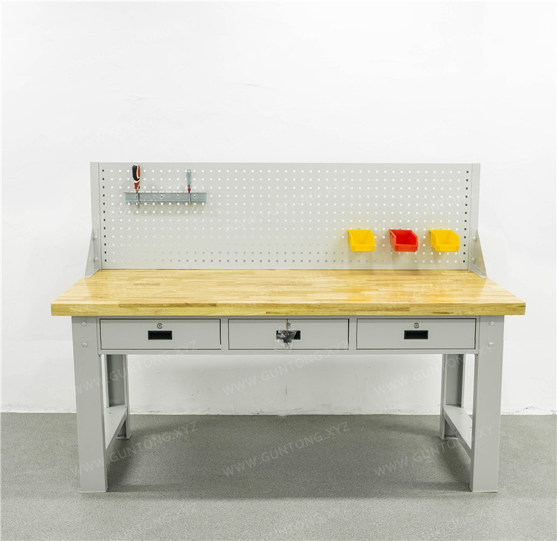
- Drawer configurations: A typical assembly workbench integrates 2 to 4 drawers with single-rail slides that open to 85% of their depth. Each drawer supports approximately 80 kg, suitable for organized storage of fasteners, small hand tools, and gauges. Drawer heights are commonly configured in 100mm and 200mm increments to accommodate different tool profiles.
- Pegboard panels: For tools that require visual management—such as calibrated torque wrenches or specialized fixtures—a square-hole pegboard mounted above or beside the workbench allows flexible hook placement and immediate visual identification of missing tools.
Zone 3: Material Infeed and Outfeed
This is where most layout failures occur. Material staging must account for the physical dimensions of incoming components, the frequency of replenishment, and the clearance needed for material handling equipment.
For small-part assembly (electronics, small automotive components), tote-based automated storage and retrieval systems (Miniload) can feed materials directly to the line-side. These systems typically handle 50–100 kg per tote with rack heights up to 12 meters, making them suitable for high-SKU environments where floor space is constrained.
For larger components, such as automotive body panels or mold bases, dedicated turnover racks or cantilever-style staging racks positioned parallel to the assembly bench reduce operator lifting and turning motions.
Spatial Constraints: Aisle Width and Bench Spacing
The most common layout mistake is underestimating aisle requirements. Here are practical minimums based on material handling method:
| Material Handling Method | Minimum Aisle Width | Notes |
|---|---|---|
| Manual cart / hand truck | 1.2–1.5 m | Allows two-way pedestrian traffic |
| Pallet jack (manual) | 2.0–2.5 m | Requires turning radius at intersections |
| Forklift (counterbalance) | 3.0–3.5 m | Must account for mast height and load overhang |
| AGV / automated guided vehicle | Per AGV specification | Typically requires dedicated lane markings |
Between adjacent workbenches in a continuous assembly line, maintain a minimum 0.8–1.0 m clearance for operator seating and chair movement. If operators stand, reduce this to 0.6 m but ensure no overhead obstructions within the reach envelope.
Load-Bearing and Structural Selection Criteria
Not every station on an assembly line requires the same load capacity. Over-specifying every workbench increases cost and reduces layout flexibility. A practical approach:
- Light assembly (electronics, small appliances): Standard composite-top workbenches with 500–800 kg total capacity are sufficient. Drawer loads of 80 kg per unit cover most tool sets.
- Medium assembly (automotive sub-assemblies, motor units): Specify C-type steel frame workbenches rated for 1,000 kg total. Add under-bench shelving for heavier component staging.
- Heavy fitting and mold work: Reinforced frames with thicker gauge steel and optional cross-bracing. Consider separate fitting benches rather than integrating heavy work into the continuous assembly line.
Standard workbench dimensions commonly available include 1500×750×800mm, 1800×750×800mm, and 2100×750×800mm (L×W×H). The 750mm depth provides adequate reach for most seated operators while keeping the bench footprint compatible with standard aisle widths.
Implementation Sequence: What to Plan First
Before ordering equipment, complete these planning steps:
- Map the material flow: Identify where raw materials enter the line, where WIP accumulates, and where finished assemblies exit. Place workbenches to minimize backtracking.
- Define the tool set per station: List every tool, fastener, and gauge required at each station. This determines whether you need 2-drawer, 4-drawer, or pegboard-integrated configurations.
- Calculate peak material staging volume: Determine how many totes, trays, or component bins must be present at each station simultaneously. This defines the required bench-adjacent storage footprint.
- Validate aisle clearances: Overlay your equipment footprint on the facility floor plan with material handling equipment turning radii.
Boundaries and Risks
- Do not assume modular workbenches can be reconfigured indefinitely.*
- Drawer slides, pegboard mounts, and frame bolt patterns are designed for specific configurations. Major changes may require new structural components.
- ESD requirements are not optional add-ons.*
- If your assembly line handles sensitive electronics, the entire workstation—including the desktop surface, chair, floor mat, and wrist strap grounding point—must be specified as an integrated ESD system from the outset.
- Automated retrieval systems require integration planning.*
- Miniload systems with 50–100 kg tote capacity need software integration with your production scheduling system. This is a separate project scope from workbench procurement.
Next Steps
If you are planning a new assembly line or reconfiguring an existing one, start by documenting your per-station tool lists, material staging requirements, and material handling equipment specifications. Guang'ErMei Precision Components provides on-site workstation planning, load-bearing design, and 6S-adapted layout services for manufacturing facilities across Guangdong Province and nationwide. Contact our engineering team with your floor plan and production volume data to receive a customized workstation equipment proposal.