
Load Bearing Requirements for Workbenches with Bench Vises: A Step-by-Step Configuration Guide
Who Needs to Worry About Vise-Induced Workbench Loads
Workshops that mount bench vises—fitter stations, automotive parts rework areas, hardware mold maintenance bays, and vocational training centers—face a specific structural challenge. A bench vise does not just add static weight; it generates concentrated clamping forces and impact loads during hammering, filing, or pressing operations. A workbench rated for uniform distributed loads may fail at the mounting point if the frame, desktop, or anchoring system is not specified for these localized forces.
This guide provides a step-by-step implementation path for selecting and configuring workbenches that safely support bench vises, based on real product parameters from Guang'ErMei Precision Components' workshop workstation lineup.
Step 1: Calculate the Total Load Demand
Before selecting a workbench, quantify the combined load the vise station must handle.
Static load components:
- Bench vise weight (typically 15–40 kg for standard 4-inch to 6-inch models)
- Workpiece weight during clamping
- Tooling and fixtures left on the desktop
Dynamic load factors:
- Clamping force transmitted to the desktop (can exceed 1,000 kg of localized pressure at the jaw contact point)
- Hammering or pressing impacts (multiply static vise weight by a factor of 2–3 for shock loading)
- Lateral torque when operators lean on or pull against clamped parts
Checkpoint: Add all static loads, then apply a 2.5× safety factor for dynamic operations. A vise station used for heavy filing and hammering should target a workbench with at least 1,000 kg total load capacity to ensure adequate margin.
Guang'ErMei's heavy-duty steel plate workbenches, such as the Single Back Panel 4-Drawer Steel Plate Workbench, are engineered with C-type cold-rolled steel frames rated for 1,000 kg total load capacity, making them suitable for vise-mounted fitter stations.
Step 2: Select the Right Desktop Structure
The desktop is the critical interface between the vise and the frame. A bench vise concentrates force on a small footprint—often just four mounting bolts spanning 150 mm × 200 mm. Standard particleboard or thin laminate desktops will crack or compress under repeated vise use.
Recommended desktop configurations for vise stations:
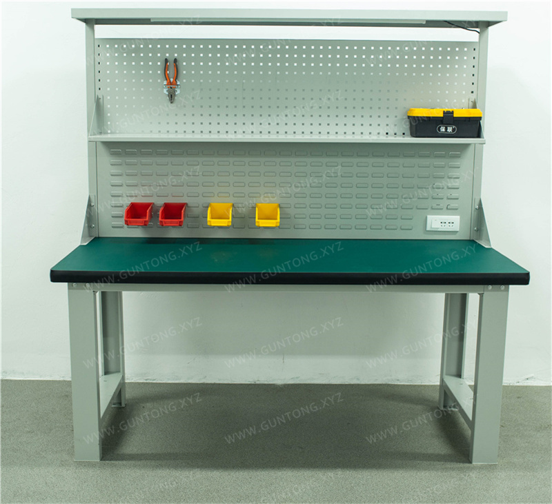
| Desktop Type | Composition | Vise Suitability |
|---|---|---|
| Steel plate composite | 5 mm raw steel plate + 45 mm high-density fiberboard + PVC edge banding | High — steel plate distributes clamping force across the fiberboard core, preventing localized crushing |
| Stainless steel | Solid stainless steel surface | High — excellent for corrosive environments, but verify sub-frame support |
| Standard laminate on MDF | Laminate + medium-density fiberboard | Low — not recommended for vise mounting without reinforcement plate |
Checkpoint: For vise stations, specify a desktop with a minimum 5 mm steel plate top layer or equivalent structural reinforcement. The steel plate composite desktop used in Guang'ErMei's fitter workbenches provides the rigidity needed to resist deformation under repeated clamping cycles.
Exception: If the application requires ESD (electrostatic discharge) protection—for example, electronics assembly with light vise work—an anti-static desktop pad can be layered over a steel plate base. The pad is grounded through a wrist strap or grounding wire connected to earth, maintaining static dissipation while the steel plate handles structural loads.
Step 3: Verify Frame Geometry and Leg Configuration
The frame must resist both vertical compression and lateral racking forces generated when operators apply torque to the vise handle or strike workpieces.
Key frame specifications to verify:
- Leg profile: C-type cold-rolled steel or square tube (e.g., 40 × 40 × 1.2 mm square tube) provides higher torsional rigidity than open-channel sections.
- Cross-bracing: Horizontal stretchers between legs prevent racking under lateral vise loads. Double-layer or stretcher-equipped frames are preferred for vise stations.
- Foot anchoring: Adjustable foot cups with floor-bolt holes allow the workbench to be anchored to concrete floors, preventing tipping or creep under heavy vise use.
Checkpoint: Confirm that the frame uses structural-grade cold-rolled steel with welded or bolted cross-members. Guang'ErMei's workbench frames use C-type cold-rolled steel construction, and lighter-duty configurations use 40 × 40 × 1.2 mm square tube frames rated for up to 300 kg, which may be sufficient for light bench vises used in electronics or inspection tasks but not for heavy fitter work.
Risk boundary: A 300 kg-rated light-duty frame is not appropriate for vise stations involving hammering or high-torque clamping. Upgrade to a 1,000 kg heavy-duty frame for these scenarios.
Step 4: Plan Vise Mounting and Anchoring
Even a correctly specified workbench can fail if the vise is improperly mounted.
Implementation steps:
- Position the vise near the front edge of the desktop, aligned with a frame leg or cross-member directly below to transfer load vertically into the frame.
- Use through-bolts with backing plates rather than wood screws or self-tapping fasteners. A steel backing plate (minimum 3 mm thick) on the underside of the desktop spreads the clamping load over a wider area.
- Torque mounting bolts to the vise manufacturer's specification and re-check after the first week of use, as initial settling may loosen fasteners.
- Anchor the workbench to the floor using expansion bolts through the adjustable foot cups, especially if the vise will be used for hammering or pressing operations.
Checkpoint: After installation, apply a test load equal to 1.5× the expected maximum clamping force and inspect for desktop deflection, bolt loosening, or frame movement.
Step 5: Configure Accessories Without Compromising Structural Integrity
Vise stations often require pegboards, lighting, drawers, and power outlets. These accessories add weight and may interfere with vise operation if not planned carefully.
Configuration guidelines:
- Pegboards and hanging panels: Mount on the back panel or upright frame, not on the desktop surface where they reduce usable vise clearance. Guang'ErMei workbenches support square-hole pegboard configurations for tool hanging and visual management.
- Drawers and cabinets: Position drawer units on the side opposite the vise to balance the load and maintain operator leg clearance. The 4-drawer tiered design available in Guang'ErMei's steel plate workbenches keeps tools organized without encroaching on the vise zone.
- Power and grounding: Route power cables through pre-drilled desk-corner holes. For ESD-sensitive environments, ensure the anti-static mat grounding wire has a dedicated earth connection separate from the power ground.
Checkpoint: Verify that the total accessory weight plus vise load does not exceed the workbench's rated capacity. Subtract accessory weight from the 1,000 kg rating to determine the remaining vise and workpiece allowance.
Common Mistakes to Avoid
| Mistake | Consequence | Correction |
|---|---|---|
| Mounting a heavy vise on a laminate desktop | Desktop crushes or cracks within weeks | Upgrade to 5 mm steel plate composite desktop |
| Using a 300 kg light-duty frame for hammering operations | Frame deformation, leg buckling | Specify 1,000 kg heavy-duty C-type steel frame |
| Positioning vise over an unsupported desktop span | Excessive deflection, bolt pull-through | Align vise with underlying frame leg or cross-member |
| Skipping floor anchoring | Workbench shifts or tips under lateral torque | Install expansion bolts through foot cups into concrete |
| Overloading with accessories | Cumulative weight exceeds frame rating | Calculate total load including all accessories before ordering |
Summary of Load Bearing Specifications by Application
| Application Scenario | Recommended Load Rating | Desktop Type | Frame Type | Floor Anchoring |
|---|---|---|---|---|
| Light electronics assembly with small vise | 300 kg | Anti-static pad on steel base | 40×40×1.2 mm square tube | Recommended |
| General fitter and maintenance work | 1,000 kg | 5 mm steel plate composite | C-type cold-rolled steel | Required |
| Heavy hammering and pressing | 1,000 kg+ | 5 mm steel plate composite | C-type cold-rolled steel with cross-bracing | Required |
| Automotive parts rework | 1,000 kg | Steel plate or stainless steel | C-type cold-rolled steel | Required |
Next Steps
If you are specifying workbenches for vise-equipped stations, start by documenting the vise model, expected clamping forces, and operational profile (filing, hammering, pressing, or light assembly). Use the checkpoints above to verify that your selected workbench meets the structural requirements at each stage—desktop, frame, mounting, and anchoring.
For non-standard vise station layouts or multi-operator fitter benches, Guang'ErMei Precision Components provides on-site workstation planning, load-bearing design, and custom manufacturing services. Contact our engineering team with your vise specifications and workshop layout to receive a tailored configuration proposal.