
Guang'ErMei Workbench On-Site Installation and Leveling Guide: Practical Steps for Workshop Setup
Who This Guide Is For
This installation reference applies to facility managers, workshop supervisors, and maintenance teams responsible for deploying heavy-duty workbenches in manufacturing environments. Whether you are setting up a new electronics assembly line, an automotive parts inspection area, or a hardware mold fitting station, correct on-site installation directly affects workstation stability, load performance, and long-term service life.
The steps below are based on Guang'ErMei Precision Components' standard installation practices for steel plate workbenches, including the Single Back Panel Single Door 4-Drawer Steel Plate Workbench series.
Pre-Installation: Site Assessment and Preparation
Before uncrating any workbench components, verify the following site conditions:
Floor Condition Check
- Flatness tolerance: The installation surface should be level within ±3 mm over a 2-meter span. Uneven floors cause frame stress and drawer misalignment.
- Load-bearing capacity: Confirm the floor can support the combined weight of the workbench, stored tools, and operational loads. A fully loaded 1800 mm steel plate workbench can exceed 1,000 kg in total operational weight.
- Surface type: Concrete floors are standard. If installing on epoxy-coated or raised access floors, use protective pads under leveling feet to prevent surface damage.
Space and Clearance Planning
- Allow at least 800 mm clearance behind the workbench for back panel access and cable routing.
- Maintain 1,200 mm front clearance for operator movement and drawer extension.
- For multi-bench layouts, plan 1,500 mm aisle width between facing workstations to support 6S workflow standards.
Component Inventory
Upon delivery, cross-check all components against the packing list:
| Component | Typical Quantity (per 1500 mm bench) |
|---|---|
| C-type cold-rolled steel frame legs | 4 |
| Cross beams and support rails | As per drawing |
| 5 mm raw steel plate + 45 mm high-density fiberboard composite desktop | 1 |
| Drawer units with slide rails | 4 |
| Back panel and door assembly | 1 set |
| Leveling feet and fastener kit | 1 set |
Step-by-Step Installation Process
Step 1: Frame Assembly
- Position the four C-type cold-rolled steel frame legs upright on the prepared floor surface.
- Connect the horizontal cross beams using the provided bolts. Tighten to 70–80% initially—full torque is applied after leveling.
- Install the lower support rails that will carry the drawer units.
Key consideration: The C-type cold-rolled steel frame is designed for a total load capacity of up to 1,000 kg. Ensure all bolt connections are seated flush before proceeding. Do not substitute fasteners with non-specified hardware.
Step 2: Leveling the Frame
This is the most critical step for long-term workstation performance.
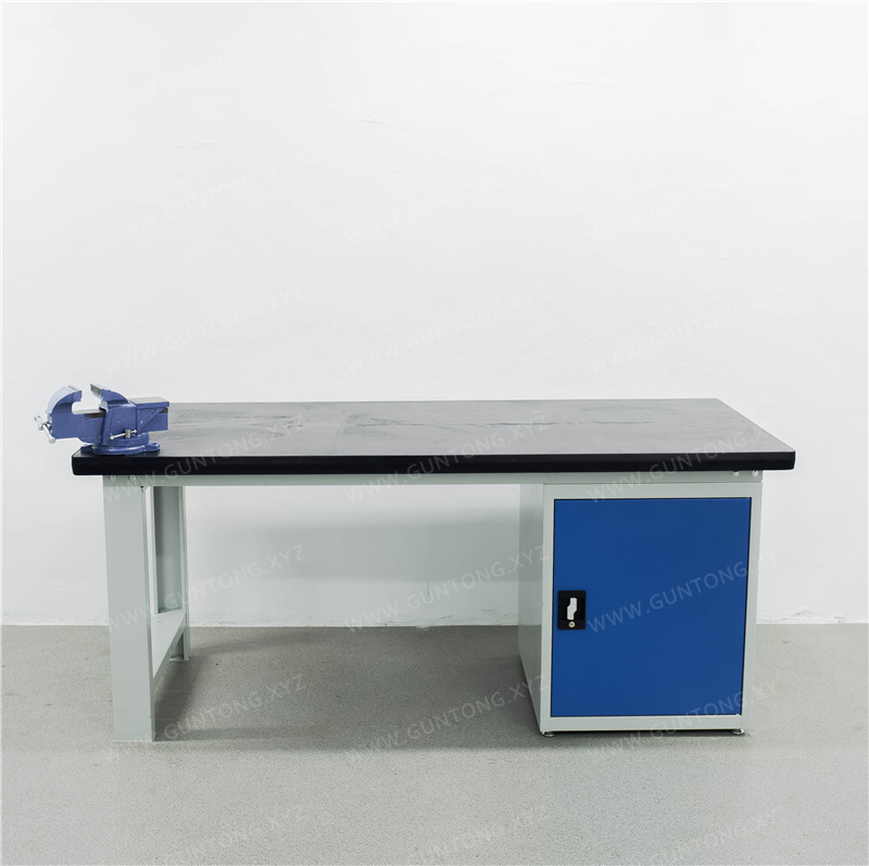
- Place a precision spirit level (minimum 600 mm length) across the top rail of the frame in both the longitudinal and transverse directions.
- Adjust each leveling foot individually. Turn clockwise to raise, counterclockwise to lower.
- Re-check level after each adjustment. Target deviation: ≤1 mm per meter.
- Once level is confirmed, tighten all frame bolts to full torque specification.
Risk boundary: If floor unevenness exceeds 5 mm across the workbench footprint, leveling feet alone cannot compensate. In such cases, request custom-length leg extensions or a site floor remediation plan before installation.
Step 3: Desktop Installation
The composite desktop consists of a 5 mm raw steel plate bonded to 45 mm high-density fiberboard with black PVC edge banding.
- With two or more personnel, lift the desktop onto the leveled frame.
- Align pre-drilled mounting holes with the frame's top rail holes.
- Secure with the provided self-tapping screws at 200 mm intervals along all edges.
- Verify that the desktop sits flush against the frame with no visible gaps.
Note: The 5 mm steel plate surface is designed for heavy-duty fitting and assembly work. Avoid dropping sharp-edged tooling directly onto the surface during initial setup to preserve the finish.
Step 4: Drawer and Door Integration
For the 4-drawer configuration (typically 100 mm × 2 + 200 mm × 2 tiered layout):
- Slide each drawer unit onto the pre-installed support rails.
- Test full extension and retraction. The drawer should move smoothly without lateral play.
- Adjust slide rail alignment if binding occurs—loosen mounting screws slightly, reposition, and retighten.
- Install the single door panel on the designated side, checking hinge alignment and latch engagement.
Each drawer is rated for an 80 kg load capacity. After installation, perform a test load with representative tooling to confirm smooth operation under working conditions.
Step 5: Back Panel and Pegboard Attachment
- Mount the single back panel to the rear frame uprights.
- If the configuration includes a square-hole pegboard section, align the mounting brackets and secure with the provided hardware.
- Verify that all hanging hooks and tool holders engage cleanly with the square holes.
Post-Installation Verification Checklist
Before releasing the workbench for production use, complete the following checks:
- [ ] Frame level confirmed in both axes (≤1 mm/m deviation)
- [ ] All fasteners torqued to specification
- [ ] Desktop flush with no movement or rocking
- [ ] All four drawers extend and retract smoothly under test load
- [ ] Door hinge and latch function correctly
- [ ] Back panel and pegboard securely mounted
- [ ] Leveling feet locked and floor contact verified at all four points
- [ ] No sharp edges or burrs exposed on accessible surfaces
Common Installation Constraints and Trade-Offs
| Constraint | Impact | Recommended Approach |
|---|---|---|
| Uneven floor (>5 mm deviation) | Cannot achieve stable level with standard feet | Request custom leg extensions or prepare floor surface |
| Limited rear clearance (<800 mm) | Difficult to access back panel for wiring or maintenance | Consider a no-back-panel configuration or relocate bench orientation |
| High-vibration environment | Fasteners may loosen over time | Schedule re-torque inspections at 30-day intervals |
| Non-standard bench dimensions | Component count and assembly sequence may differ | Follow the project-specific installation drawing provided by Guang'ErMei |
When to Request Professional Installation Support
While standard-size workbenches (1500 × 750 × 800+500 mm, 1800 × 750 × 800+500 mm, 2100 × 750 × 800+500 mm) can be installed by in-house maintenance teams following this guide, the following scenarios warrant Guang'ErMei's on-site installation service:
- Multi-bench integrated layouts requiring precise alignment across a production line.
- Non-standard custom workbenches with modified dimensions, specialized desktop materials, or integrated utility routing.
- Facilities with strict safety or audit requirements where installation documentation and sign-off are mandatory.
Guang'ErMei provides full-chain service from product design and manufacturing through on-site installation and after-sales support, covering workstation planning, load-bearing design, and 6S adaptation for manufacturing environments across electronics, automotive, hardware mold, and maintenance testing sectors.
Next Steps
If you are planning a workstation deployment and need installation guidance specific to your facility layout, contact Guang'ErMei Precision Components to discuss your project requirements. Our engineering team can provide site-specific installation drawings, load-bearing calculations, and on-site support scheduling.